- 您现在的位置:买卖IC网 > Sheet目录299 > 71M6543F-IGT/F (Maxim Integrated Products)IC ENERGY METERING
�� �
�
�71M6543F/71M6543G� Data� Sheet�
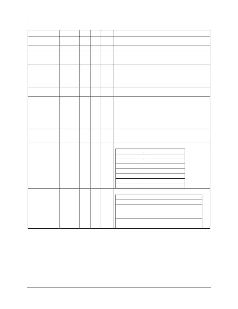
�Table� 52:� LCD� Configurations�
�Name�
�LCD_ALLCOM�
�LCD_BAT�
�LCD_E�
�LCD_ON�
�LCD_BLANK�
�LCD_RST�
�LCD_DAC[4:0]�
�LCD_CLK[1:0]�
�Location�
�2400[3]�
�2402[7]�
�2400[7]�
�240C[0]�
�240C[1]�
�240C[2]�
�240D[4:0]�
�2400[1:0]�
�Rst�
�0�
�0�
�0�
�0�
�0�
�0�
�0�
�0�
�Wk�
�–�
�–�
�–�
�–�
�–�
�–�
�–�
�–�
�Dir�
�R/W�
�R/W�
�R/W�
�R/W�
�R/W�
�R/W�
�R/W�
�R/W�
�Description�
�Configures� all� 6� SEG/COM� pins� as� COM.� Has� no� effect�
�on� pins� whose� LCD_MAP� bit� is� zero.�
�Connects the LCD power supply to VBAT in all modes.�
�Enables� the� LCD� display.� When� disabled,� VLC2,�
�VLC1,� and� VLC0� are� ground� as� are� the� COM� and� SEG�
�outputs� if� their� LCD_MAP� bit� is� 1.�
�LCD_ON� =� 1� turns� on� all� LCD� segments� without�
�affecting� the� LCD� data.� Similarly,� LCD_BLANK� =� 1�
�turns� off� all� LCD� segments� without� affecting� the� LCD�
�data.� If� both� bits� are� set,� all� LCD� segments� are� turned�
�on.�
�Clear� all� bits� of� LCD� data.� These� bits� affect� SEGDIO�
�pins� that� are� configured� as� LCD� drivers.�
�This� register� controls� the� LCD� contrast� DAC� which�
�adjusts� the� VLCD� voltage� and� has� an� output� range� of�
�2.65� VDC� to� 5.3� VDC.� The� VLCD� voltage� is�
�VLCD� =� 2.65� +� 2.65� *� LCD_DAC[4:0]� /31�
�Thus,� the� LSB� of� the� DAC� is� 85.5� mV.� The� maximum�
�DAC� output� voltage� is� limited� by� V3P3SYS,� VBAT,� and�
�whether� LCD_BSTE� is� set.�
�Sets� the� LCD� clock� frequency� (1/T).� See� definition� of� T�
�in� Figure17. Note: fw=32768Hz�
�00-fw/2^9,� 01-fw/2^8,� 10-fw/2^7,� 11-fw/2^6�
�The� LCD� bias� and� multiplex� mode.�
�LCD_MODE[2:0]� 2400[6:4]�
�0�
�–�
�R/W�
�LCD_MODE�
�000�
�001�
�010�
�011�
�100�
�101�
�110�
�Output�
�4� states,� 1/3� bias�
�3� states,� 1/3� bias�
�2� states,� ?� bias�
�3� states,� ?� bias�
�Static� display�
�5� states,� 1/3� bias�
�6� states,� 1/3� bias�
�This� register� specifies� how� VLCD� is� generated.�
�LCD_VMODE[1:0]� 2401[7:6]�
�00�
�00�
�R/W�
�LCD_VMODE�
�11�
�10�
�01�
�00�
�Description�
�External� VLCD�
�LCD� boost� and� LCD� DAC�
�enabled�
�LCD� DAC� enabled�
�No� boost� and� no� DAC.�
�VLCD� =� VBAT� or� V3P3SYS�
�The� LCD� can� be� driven� in� static,� ?� bias,� and� 1/3� bias� modes.� Figure� 17� defines� the� COM� waveforms.�
�Note� that� COM� pins� that� are� not� required� in� a� specific� mode� maintain� a� segment� off� state� rather� than�
�GND,� VCC,� or� high� impedance.�
�The� segment� drivers� SEGDIO22� and� SEGDIO23� can� be� configured� to� blink� at� either� 0.5� Hz� or� 1� Hz.�
�The� blink� rate� is� controlled� by� LCD_Y� (I/O� RAM� 0x2400[2])� .� There� can� be� up� to� six� pixels/segments�
�connected� to� each� of� these� driver� pins.� The� I/O� RAM� fields� LCD_BLKMAP22[5:0]� (I/O� RAM� 0x2402[5:0])�
�and� LCD_BLKMAP23[5:0]� (I/O� RAM� 0x2401[5:0])� identify� which� pixels,� if� any,� are� to� blink.�
�LCD_BLKMAP22[5:0]� and� LCD_BLKMAP23[5:0]� are� non-volatile.�
�v2�
�63�
�发布紧急采购,3分钟左右您将得到回复。
相关PDF资料
71M6545-IGT/F
IC ENERGY METERING
720-10007-00300
CBL D-SUB 9PIN FMAL-25PIN FML 3M
720-10010-00025
CBL DSUB 9PIN FML-25PIN MAL .25M
720-10020-00300
CBL DSUB 9PIN FML-9PIN MALE 3M
720-10021-00300
CBL DSUB 9PIN FML-9PIN FEMAL 3M
72231-0881
8 POS T/P SHLD 4 GR ASSY
7250B
PANEL KIT BOTTOM FOR R-1220 CASE
731-10061-00200
CBL DSUB HD 15FEMAL-15MALE 2.0M
相关代理商/技术参数
71M6543F-IGTR/F
功能描述:计量片上系统 - SoC Precision Energy Meter IC
RoHS:否 制造商:Maxim Integrated 核心:80515 MPU 处理器系列:71M6511 类型:Metering SoC 最大时钟频率:70 Hz 程序存储器大小:64 KB 数据 RAM 大小:7 KB 接口类型:UART 可编程输入/输出端数量:12 片上 ADC: 安装风格:SMD/SMT 封装 / 箱体:LQFP-64 封装:Reel
71M6543FT-IGT/F
制造商:Maxim Integrated Products 功能描述:ENERGY METER ICS - Rail/Tube
71M6543FT-IGTR/F
制造商:Maxim Integrated Products 功能描述:3-PHASE SOC, 64KB FLASH, PRES TEMP SENSOR - Tape and Reel
71M6543G
制造商:MAXIM 制造商全称:Maxim Integrated Products 功能描述:Selectable Gain of 1 or 8 for One Current Energy Meter ICs Metrology Compensation
71M6543GH
制造商:未知厂家 制造商全称:未知厂家 功能描述:电表IC
71M6543GHT-IGT/F
制造商:Maxim Integrated Products 功能描述:3-PHASE, 128KB, PRES TEMP SENSOR, HI PREC - Bulk
71M6543GHT-IGTR/F
制造商:Maxim Integrated Products 功能描述:3-PHASE, 128KB, PRES TEMP SENSOR, HI PREC - Tape and Reel
71M6543G-IGT/F
功能描述:计量片上系统 - SoC Precision Energy Meter IC RoHS:否 制造商:Maxim Integrated 核心:80515 MPU 处理器系列:71M6511 类型:Metering SoC 最大时钟频率:70 Hz 程序存储器大小:64 KB 数据 RAM 大小:7 KB 接口类型:UART 可编程输入/输出端数量:12 片上 ADC: 安装风格:SMD/SMT 封装 / 箱体:LQFP-64 封装:Reel